
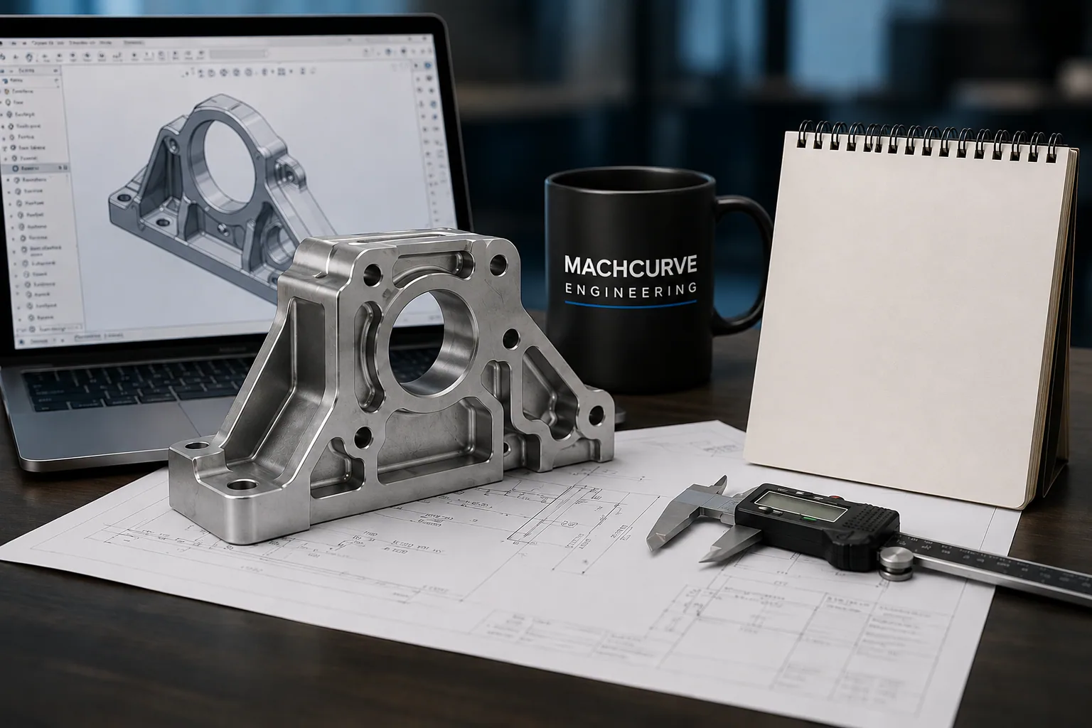
A part can be geometrically perfect and still be expensive to make. By the time a model reaches production, roughly 70% of its final cost is already committed by design decisions — material, tolerances, feature geometry, and the number of setups a machinist needs. Design for Manufacturing (DFM) is the discipline of making those decisions deliberately rather than discovering them in a quotation.
The checklist below is the review we run on every model before it leaves our desk. It is deliberately boring: most manufacturing problems are not exotic, they are the same handful of oversights repeating across projects.
1. Question every tight tolerance
Tolerance is the single most expensive line item a designer controls. Tightening a dimension from ±0.1 mm to ±0.01 mm can multiply the cost of a feature several times over, because it changes the process, the tooling, and the inspection required. Every tight tolerance on a drawing should be traceable to a functional requirement — a bearing fit, a seal, a mating interface. If nobody can name the requirement, it does not belong there.
2. Reduce the number of setups
Each time a part must be unclamped, rotated, and re-fixtured, you pay for machine time and you introduce a new stack of positional error. Features that can be reached from a single direction are cheaper and more accurate than features scattered across five faces. When you place a hole on the far side of a part, ask whether it has earned the extra setup.
3. Design around standard tooling
Internal corners must have a radius, because the end mill cutting them is round. Specifying a sharp internal corner forces either EDM or a custom tool, both of which are avoidable costs. As a rule of thumb, use the largest corner radius the design will tolerate, and keep pocket depths within about four times the tool diameter so a standard-length cutter can reach the floor without chatter.
4. Keep wall thickness uniform
This matters most in moulding and casting, where thick sections cool more slowly than thin ones. The result is sink marks, internal voids, and warping. Where a thick section is structurally necessary, core it out and add ribs rather than leaving a solid mass of material.
5. Confirm the part can actually be assembled
A model that mates perfectly in CAD can be impossible to build by hand. Check that a fastener has clearance for a driver, that a technician can physically reach a screw, and that the sequence of assembly does not require a part to pass through another one.
The review, in short
- Every tight tolerance maps to a stated functional requirement
- Features are grouped to minimise machine setups
- Internal corners carry a radius suited to standard tooling
- Pocket depth stays within roughly 4× the tool diameter
- Wall thickness is uniform; thick sections are cored and ribbed
- Fasteners have tool clearance and a viable assembly sequence
- Material and finish are specified, not assumed
- Drawings carry GD&T where fit and function depend on it
The cheapest design change is the one made in CAD. The most expensive is the one made after the tool is cut.
None of this requires exotic software. It requires a designer who has spoken to a machinist. If you are unsure whether a design is production-ready, a DFM review before release is a fraction of the cost of a tooling revision after it.