It is a common situation in plants that have been running for decades. A component fails, the supplier who made it has closed or moved on, and nobody can find a drawing — often because one was never produced. The machine is still in service, and the part must be reproduced from the only reference that exists: the part itself.
Reverse engineering is the process of turning that physical object back into engineering intent. Done carelessly it produces a model that copies the wear on a worn part. Done properly it produces something better than the original: a parametric model you can manufacture, modify, and improve.
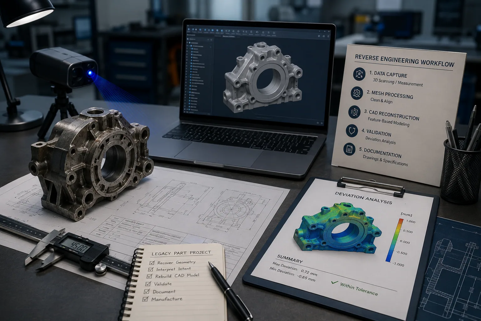
Step 1 — Capture the geometry
For a simple prismatic part, calipers, micrometers, and a height gauge are entirely sufficient, and often more accurate than a scan. For organic or freeform surfaces — a turbine blade, a cast housing, an ergonomic handle — 3D scanning is the practical route. The scan produces a point cloud, which becomes a mesh: a dense, accurate record of the surface as it exists today.
Step 2 — Separate intent from artefact
This is the step that separates a good reverse engineering job from a bad one, and it cannot be automated. A scanned mesh faithfully records everything about the part, including things that were never intended: wear on a bearing surface, a burr, a casting defect, corrosion, a repair somebody made with a file fifteen years ago.
The engineer's job is to look at a measured diameter of 24.94 mm and recognise the designer meant 25 mm. A hole that scans at 6.05 mm was drilled with a 6 mm bit. A face that scans slightly convex was meant to be flat. Copying the mesh exactly reproduces the defects; interpreting it recovers the design.
A scan tells you what the part became. Engineering judgement tells you what it was meant to be.
Step 3 — Rebuild it parametrically
The mesh is then used as a reference to build a clean, feature-based CAD model — sketches, extrusions, revolves, fillets, with a proper feature tree. The result is a model that can be edited. If a boss needs to move 2 mm, you change a dimension rather than re-sculpting a mesh. This is what makes the deliverable an asset rather than a snapshot.
Step 4 — Validate against the original
The rebuilt model is compared back against the scan data as a deviation map, which shows where the clean model departs from the physical part and by how much. Small, deliberate deviations are expected — you have removed wear and restored nominal dimensions. Large or unexplained ones mean a feature has been misread and must be revisited.
Step 5 — Document it properly
Finally the part gets what it never had: a full drawing with dimensions, tolerances, GD&T where fit matters, material specification, and surface finish. Where the original material is unknown, it is either tested or inferred from the application. The output is a package any competent shop can quote from and manufacture.
What you should expect to receive
- A clean, parametric 3D CAD model with an editable feature tree
- Manufacturing drawings with tolerances and GD&T
- A deviation report comparing the model to the scanned part
- Material and surface finish specification
- Neutral exchange formats (STEP / IGES) for any downstream vendor
The point of the exercise is not merely to replace one broken component. It is to stop being dependent on a part nobody has the drawings for — so that the next time it fails, it is a purchase order rather than a project.